
The CandyFab Project
3D Printing in Sugar. Big, DIY, and on the cheap. 2006 — 2009.
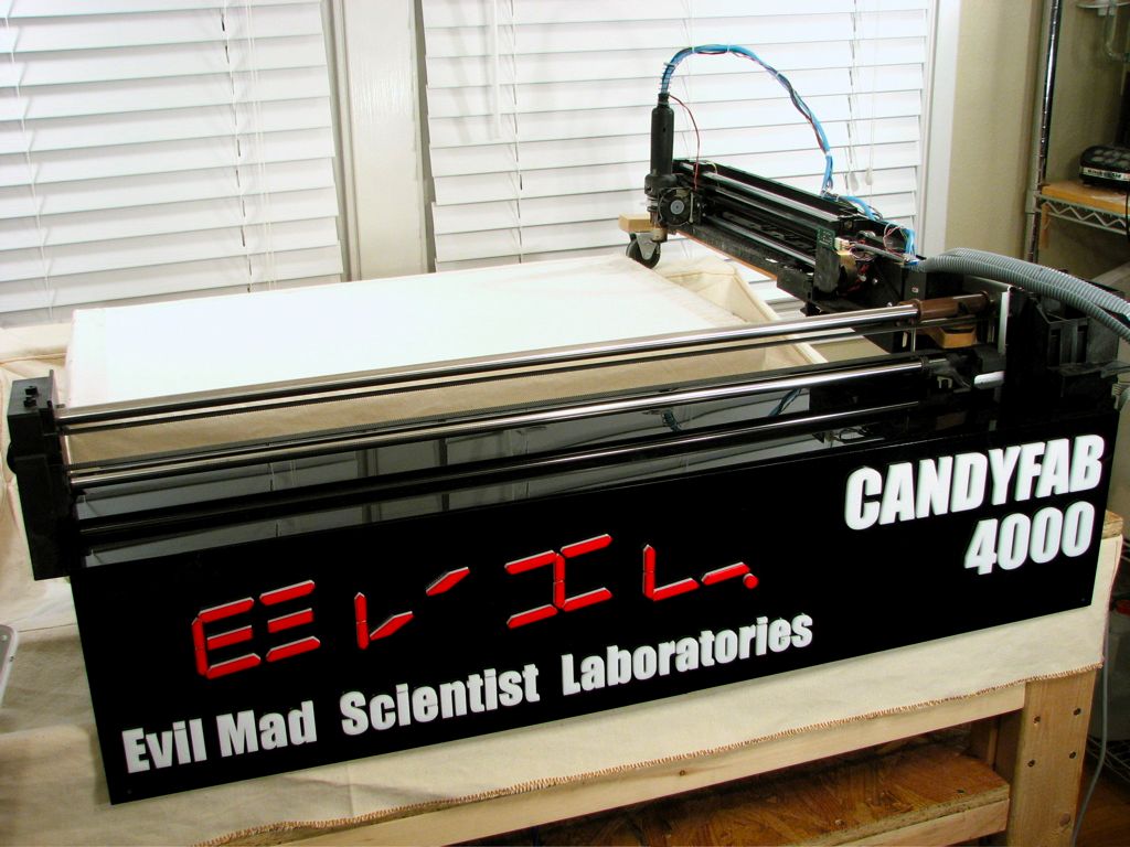
The CandyFab 4000, 5000, and 6000 were early DIY 3D printers, built as hobby projects in the years 2007, 2008, and 2009, respectively, by Windell Oskay and Lenore Edman of Evil Mad Scientist Laboratories.
CandyFab machines were able to print very large objects out of pure sugar, very inexpensively, by melting sugar grains together with hot air, using a novel process called selective hot air sintering and melting (SHASAM). The general idea of the build process, that of stacking solid two-dimensional printed layers, is common to all 3D printing methods. CandyFab, like other powder-based printers, begins with a bed of granular printing media — typically granulated sugar.
Using a narrow, directed, low-velocity beam of hot air, the CandyFab selectively fuses together the print media grains, forming a two-dimensional image out of fused media. We then lower the bed by a small amount, add a thin flat layer of media to the top of the bed, and selectively fuse the media in the new layer, forming a two dimensional image that is also fused to any overlapping fused areas in the layer below. By repeating this process, a three-dimensional object is slowly built up. At the end of the build, the bed is raised up to its original position, disinterring the fabricated model, while unused media is reclaimed for use in building the next object.
The CandyFab 4000
Inspiration / 3D printing in 2006
In the spring of 2006, we attended the very first Maker Faire, which was held in San Mateo California. We exhibited our very own Interactive LED Dining Table project there, and got hooked on all things Maker Faire. Amongst the things that we saw there were incredible 3D printed metal mathematical sculptures by Bathsheba Grossman. We had never seen anything like them. We came away from Maker Faire with a solid idea for next year: to make our own 3D printer.
At the time, 3D printing wasn’t in the mainstream consciousness the way that it is today. Even the term “3D printing” itself had a different meaning — it was a trademarked phrase that referred to one particular fabrication process. At least, it was supposed to. In practice, “3D printing” is such a good and practical term for all the different kinds of additive manufacturing processes that it stuck, and now encompasses everything from traditional stereolithography to direct metal printing. But in 2006, you were more likely to hear someone talk about “rapid prototyping” or occasionally “solid freeform fabrication.” For example, RepRap was already around, but you wouldn’t have found the phrase “3D printer” on its home page.
Commercial 3D printers (from Stratasys, Z Corp., and others) were on the market, but starting at around $20k, they were simply unattainable on a hobby budget. There were just a few DIY-oriented 3D printing kits around as well (e.g., RepRap and Fab@Home), but they were still mostly in the $1-3k range.
For our own project, we wanted something that would let us fabricate big 3D models. Most of the homebrew 3D printers at the time were extruders (“fused deposition modeling” machines), making tiny, precise plastic models. While that can be scaled up, a secondary concern was the cost of the special filaments that they used, which were not in wide distribution and ranged in price up to several dollars per cubic inch. If we wanted to make big models, it would be nice to be able to use easily available, lower-cost media.
A separate question is about which fabrication technology to use. Each has its own challenges: UV-curing resins are messy, lasers can be expensive and potentially dangerous, plastic fumes are smelly, inkjet heads are hard to control, and extruders can’t make overhanging parts very well. And all of it was expensive and a patent minefield, which would both be concerns if we ever did make a kit version of our project.
Of the choices, the powder-bed methods − used in selective laser sintering and in systems that printed binders with inkjet heads − seemed the cleanest and most capable. A great choice, so long as the difficulties with the print media, lasers, and/or print heads could be solved.
Just add sugar, just add heat.
If you think about it for a moment, sugar is a particularly good print medium because it’s easy to obtain, low in cost, kid friendly, water soluble, non-hazardous, non-toxic, non-intimidating, rigid despite having a low melting point, and potentially suitable for making objects for lost sugar (like lost wax) investment casting.
It is also possible to make interesting food with this technology.
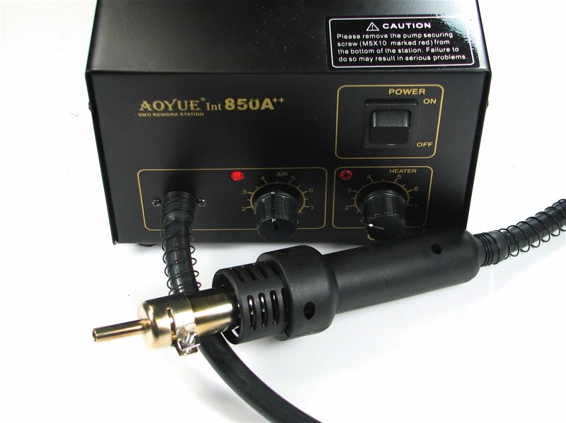
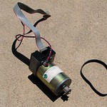
To melt and fuse the sugar, we used a modified hot air rework (soldering) station. An equivalent could be made by using just its replacement air heating element (500 W, $10) with a $5 aquarium air pump. Of course, it also needs a housing and a control system that can provide a the chosen amount of power to the heating element. We have seen that the element can be driven directly from 120 V, with duty cycle controlled by an inexpensive digital relay. The heater element is hardly new technology; it’s the baby sister of the one in your hair dryer. None the less, it’s well designed and quite suitable for this application.
One detail to consider: Most hot air sources are designed for a relatively high air flow rate. But, for our purpose — blowing hot air at sugar not to move it but just to melt it — getting better performance means that we want high heat but very flow air flow rate. In a hair dryer (or hot air rework station handpiece), it’s the air flowing through that cools the unit and makes it safe to use. When you turn down the air flow rate, you have to make sure that your heater doesn’t melt or otherwise self destruct.
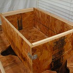
Building the CandyFab 4000
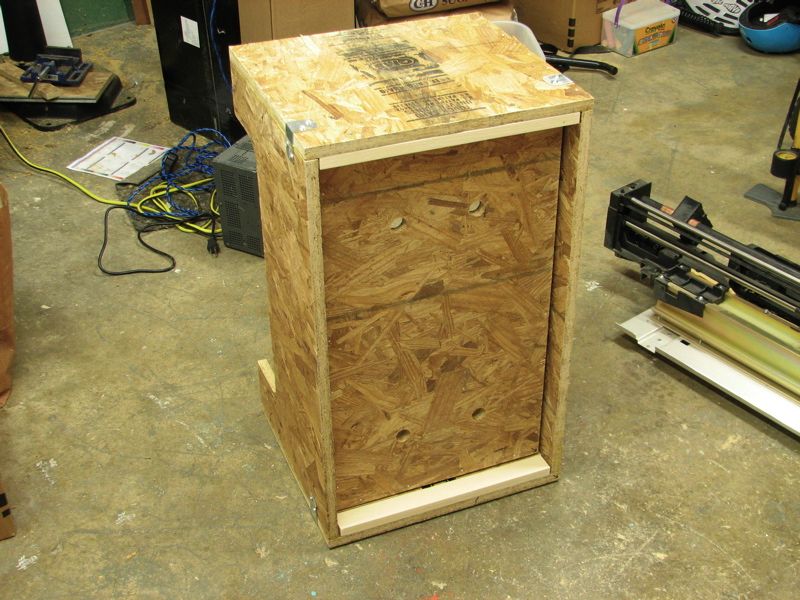
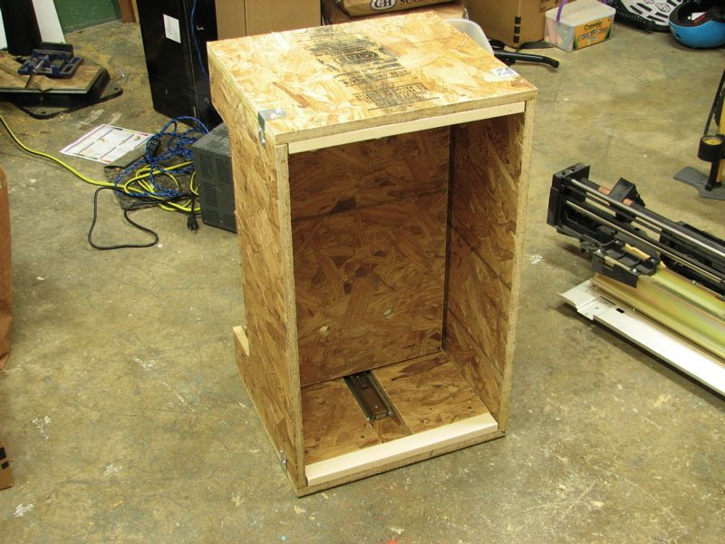
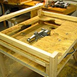
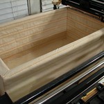
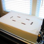
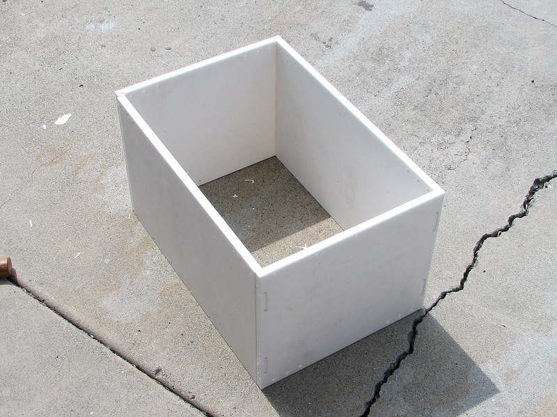
Like other 3D printers, ours works by stacking layers of 2D images. We begin with a flat bed of sugar and “print” a 2D design into it by selectively fusing the sugar. The bed is then lowered slightly, a new layer of sugar is added, and the next 2D image is printed, fusing with the layer below. This process is repeated to build up the three-dimensional image. Our machine makes the vertical translation possible by providing a large, five-sided wooden box with a floor that can move up and down on drawer slides.
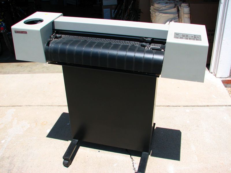
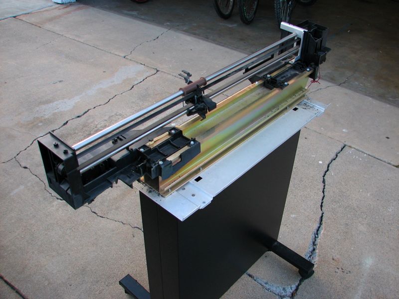
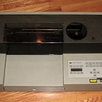
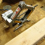
The X and Y axis motion control systems were based on belt drives and quadrature-encoded motors recycled from old HP plotters, while the Z axis is based on a modified automotive jack. This isn’t necessarily the best way to do things, but it was cost effective. The overall project budget was about $500.
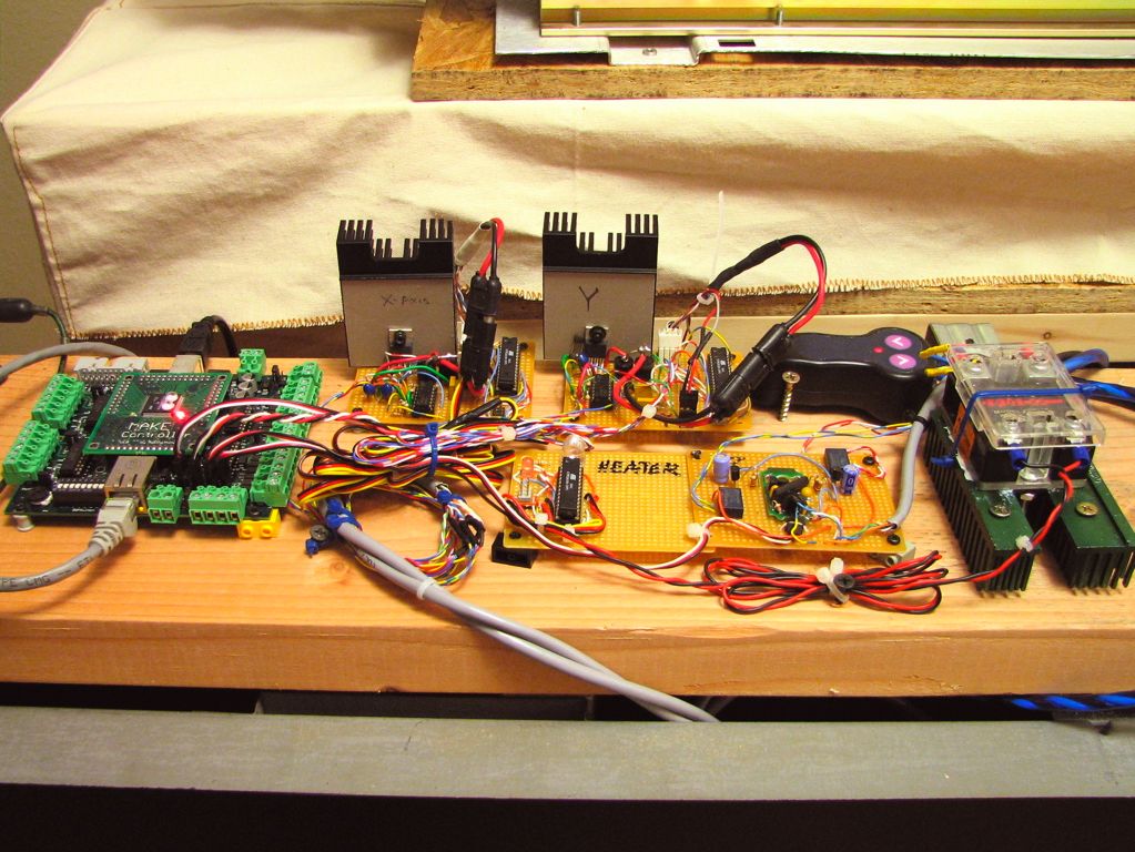
Custom closed-loop, high-power drive electronics were designed to power each of the three axes and accept position commands, using standard hobby servo PWM control code. The X and Y axes each had their own hand-wired board with an ATmega168 microcontroller, reading the quadrature outputs from the motor, and PWM “analog” output, to a linear power amplifier that drove each motor. Computer control and interface were provide through a MAKE Controller, an ARM based I/O board that was popular at the time.
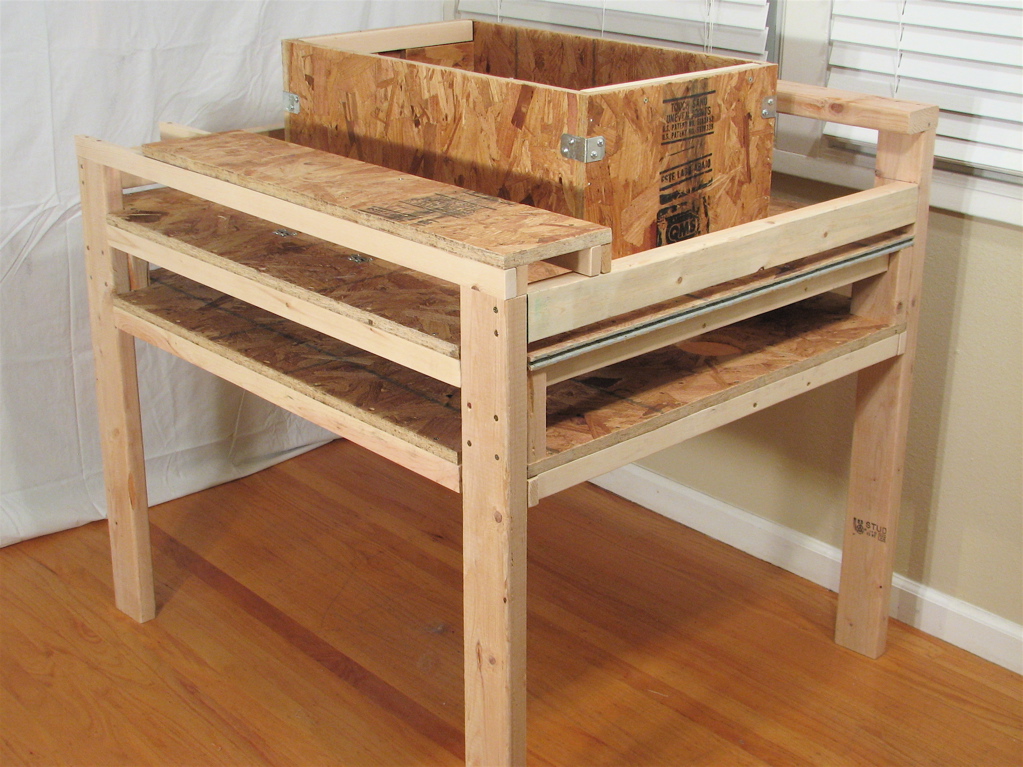
We designed the frame of the machine in Sketchup and built it in our garage from plywood and lumber. It doesn’t take high-tech tools to do stuff like this. We used the tools that we had: a power drill and a drill press, a jigsaw, and a hand sander.
Form follows function: The wooden base was sized to fit the particular HP pen plotters that we had disassembled, and the center part was designed to support the giant piston, and the one-ton servo motor that raises and lowers it.
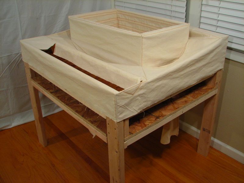
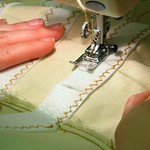
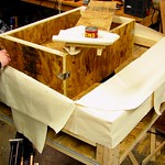
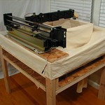
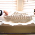
Atop the wood sits a flexible canvas liner. It lines the piston to prevent sugar from leaking out in strange places and assists in recovering unused media.
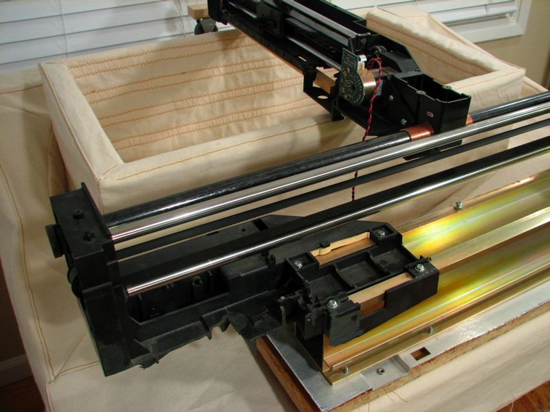
After the liner, the X and Y stages are added. The Y-axis belt-drive system is mounted, on one end, to a linear bearing that slides along a steel rail. That bearing is pushed by the belt-driven carriage on the X axis, through a rubber band low-cost flexible rubber coupling. The other end of the Y-axis belt-drive system is supported by a free-rolling rubber wheel from the hardware store.
You can read more about the build process in this blog post and in our main announcement about the CandyFab 4000. See more pictures in this flickr set.
Finally, CNC Toast
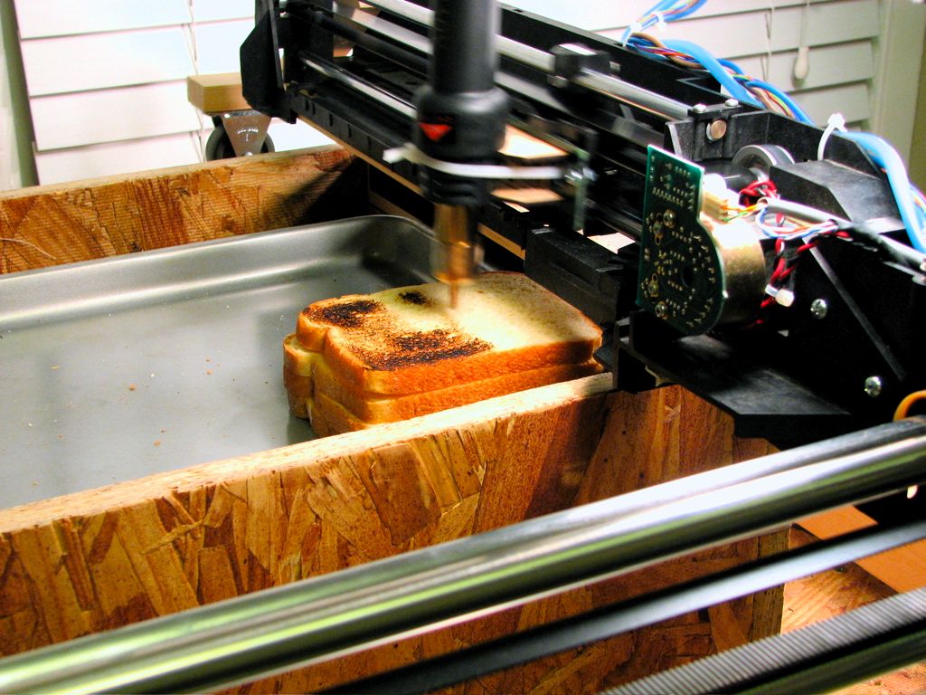
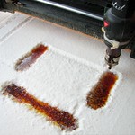
The hot air gun is mounted to the belt-driven carriage on the Y axis of the printer. In final testing, we needed to test the performance of the XY stage and of the hot air gun. That’s quite easy to do by simply moving the Z stage out of the way.
The intermediate result was surprisingly fun: a genuine CNC toaster!


3D Printing with the CandyFab 4000
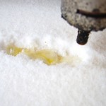
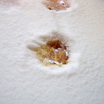
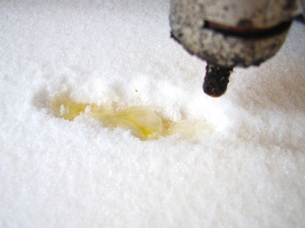
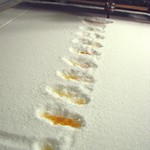
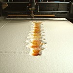
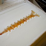
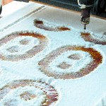
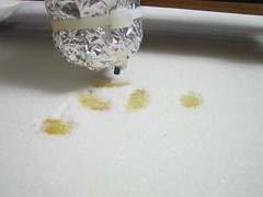
The printing process begins by drawing a thin line with the heater element, fusing the sugar together. The width of the line drawn in these first tests was about 3 mm, and defined our minimum feature size. For each pixel that we want to fuse, we hold the hot air gun over that point for a period of time, typically between one and three seconds, depending on air temperature settings and the thickness of the layer that we want to fuse.
At each stage of the print, there is some exposed, fused sugar. It has a glassy surface of amorphous sugar. The top layer is about 1/8 of an inch (3 mm) thick and is uniformly colored a light golden brown– caramelized in the melt process. Spots that appear darker overlap (or partially overlap)– and are fused to– the layers below them, because we are looking into a deeper layer of colored sugar.
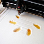
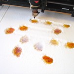
Because the hot air gun blows air continuously, it leaves a shallow trail of disturbed (but not melted) sugar wherever it goes − even between areas that it melts. Excess fusion was not an issue so long as “rapid moves” between areas to be fused were actually rapid.
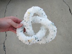
This toroidal coil sculpture was one of the first objects that we made with the CandyFab. It is already big, but to give you a sense of scale, four of these could be fabricated simultaneously within the printable volume.
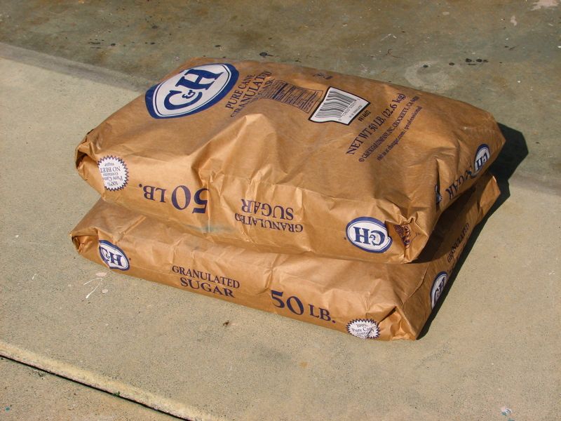
The CandyFab 4000 had a maximum printable volume of 24 x 13.5 x 9 inches (61 x 34 x 23 cm)– 2916 cubic inches, or 1.7 cubic feet. Beyond just lowering the media cost of a given fabricated object, using a low-cost medium can be leveraged to make large-volume printing both practical and economical. Filling the bed of the CandyFab 4000 takes a little more than 100 pounds of sugar, which costs about $37 retail. For comparison, the fine nylon powders used by high quality SLS (selective laser sintering materials) tend to cost upwards of $25 per pound. Even accounting for its lower density, filling the bed with nylon powder would still cost about $700.
If you look closely, you can see the pixelated nature of our fabricated object. The bulk of the material is solid, glassy, lightly caramelized sugar. It feels and acts very much like regular glass. It smells great. The outside surface is covered by loosely attached sintered sugar (white), and can be removed or smoothed over by hand.
A giant model of a wood screw, and a modest dodecahedron.
When printing the early layers of the wood screw, just the edges of the threads are visible. It’s a philips-head screw, so the broad cross sections where you only see a single slot must be just above or just below the center of the model. When it finishes printing, the bed raises in order to allow the humans to extract the model. Even after raising the piston up, some digging is still required to get the last ten pounds of sugar off the top. For reference, the print media cost for the giant screw model is under one dollar.
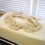
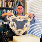
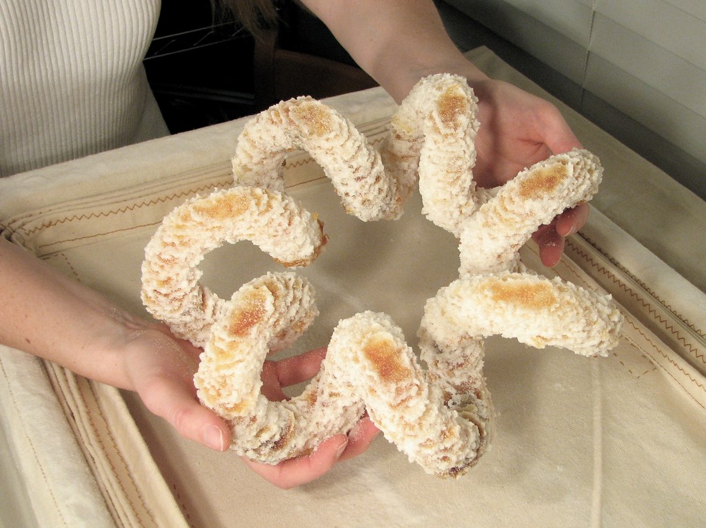
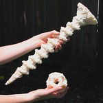
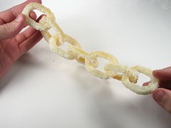
In 3D printing, it is practical to make complex shapes that cannot be efficiently manufactured by traditional subtractive processes, where material is cut away from a block to make an object. Consider a chain of connected links. While skilled whittlers can indeed carve a chain out of a single piece of wood, it’s a labor intensive process that requires accessing the part from many different angles. In contrast, in an additive process it is no more difficult to make a connected chain than it is to make any other shape. To prove the point, we constructed this chain of 12 links– using about a pound of sugar per link.
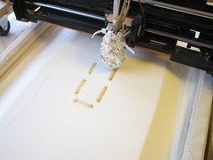
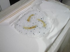
When we first start to build up the chain, we are only printing the lowest part of the six chain links that are vertically oriented; it’s hard to see from the pattern of melted sugar alone how this will turn into a chain. In the middle section of the chain, where we are printing parts of all twelve links, it is a little more obvious.
One thing to note is that the loose “horizontal” links are suspended by the loose print medium (sugar) in the print bed. This is in contrast to some other fabrication technologies which require a separate support matrix to be built alongside the actual desired object.

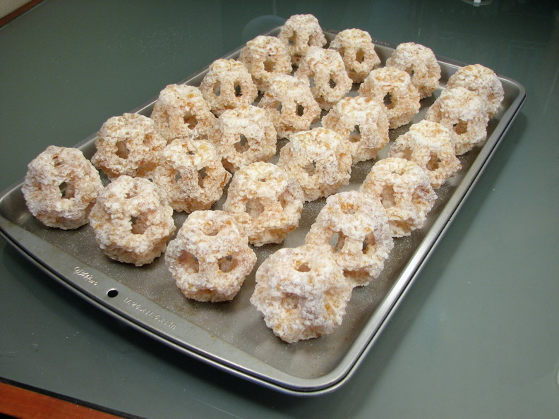
An array of fat, low-resolution dodecahedrons, printed as giveaways and test objects. (Question: Can you smooth the surface by warming the pieces in the oven? Answer: no.) Wider beams made them less likely to break upon handling, and we could turn up the heat and speed when precision was less critical.


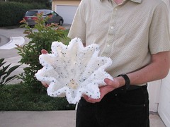
The sculpture Soliton by Bathsheba Grossman (model used by kind permission).


A ¾ twist mobius strip with a square cross section and windows cut at regular intervals in all of the sides. Even though it’s hollow, it still weights nearly eight pounds— that’s a lot of sugar.
It was at about this stage that we brought the CandyFab 4000 to the 2007 Bay Area Maker Faire, where it was a hit indeed. There were four 3D printers there that year: The CandyFab, a $20k Stratasys Dimension, Fab@Home, and a couple of avid hackers making excellent progress with a hot glue gun and XYZ stage. Some pictures at the event: 1, 2, 3, 4.
Improving precision
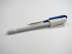
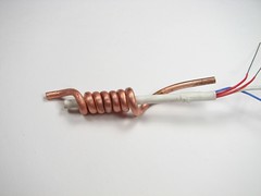
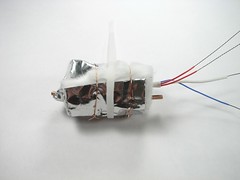
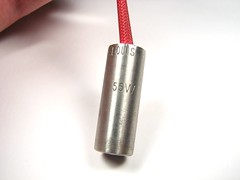
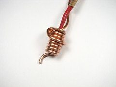
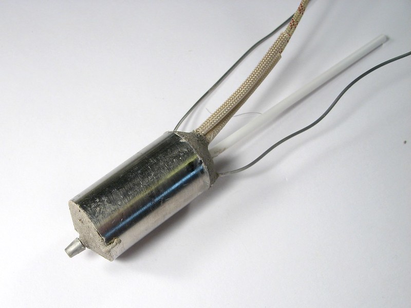
CandyFab Heater versions 2.0 and 2.1 were based around commercially available sealed heating elements: a beautifully made 24V, 50 W ceramic element made by Hakko (model A1321) and a standard 55W cartridge heater. Both had their pros and cons. Around the heating element, we wrapped several windings of 1/8″ OD soft copper refrigeration tubing and a bundle of high-temperature insulation. Copper is not actually a good choice for the tubing here, since it oxidizes rapidly with high temperature air flow, and these heater assemblies had a very short life. Pro-tip: Use stainless steel tubing for hot air.
Other considerations aside, this heater gave us the precision and control to take CandyFab to the next level.

Same model, much finer quality. Our estimate was that the effective pixel size was reduced from about 1/5″ (5 mm) to about 1/16″ (1.6 mm).
This was starting to get interesting. Now we could make a tiny chain of movable links of sugar.
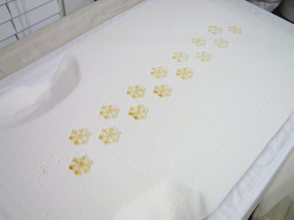
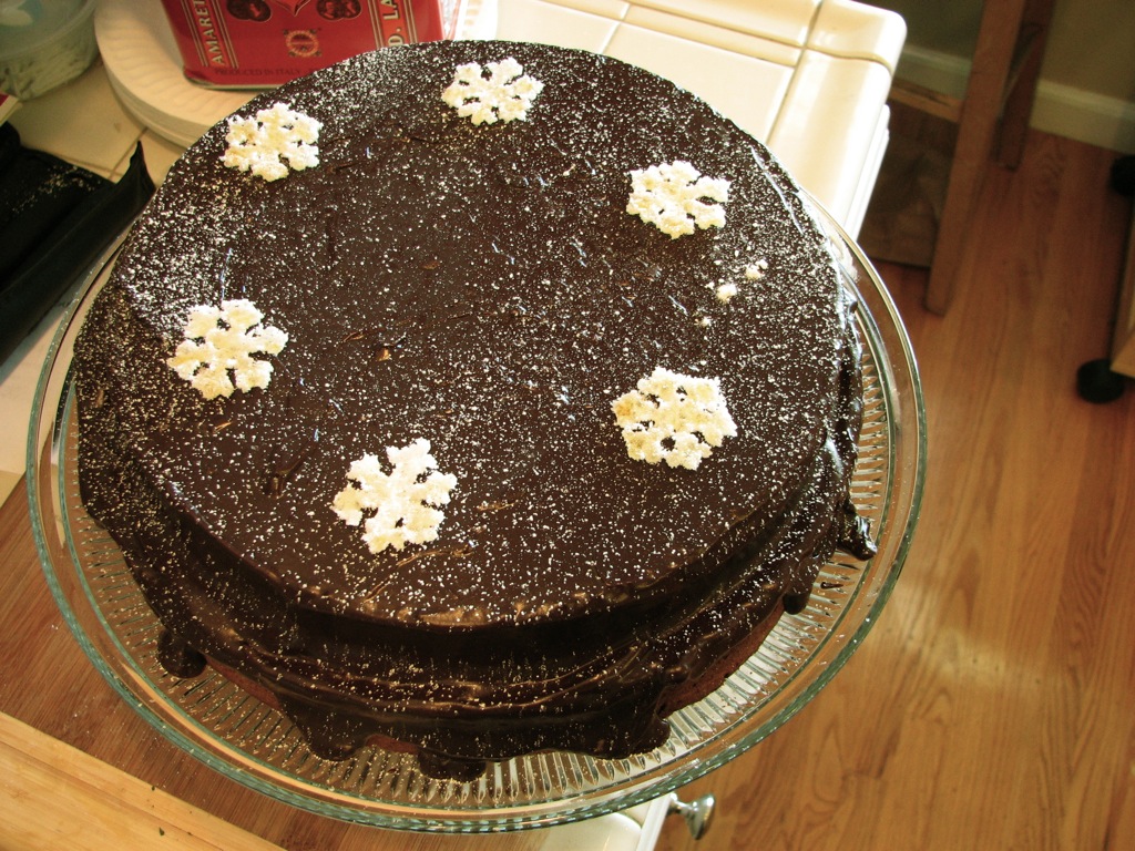
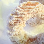
We had also by this point audited all of the materials in the sugar and air paths to make sure that everything was genuinely food safe. The new resolution was also a big advantage: Nobody wants to eat a pound of sugar, but we could at least print simple decorations for a birthday cake.
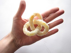
We also began to experiment with printing plastic, using a hybrid method with plastic pellets resting on a bed of sugar. Upside: More permanent. Downside: Doesn’t smell as nice. We made a trefoil knot and a fruit bowl from HDPE pellets this way. (The dark dots are green colored HDPE pellets.)
The CandyFab 5000; the lost year

The CandyFab 5000 was a complete design departure from the CF4k, using new off-the-shelf parts wherever possible. Additionally, effort was made to use components and materials that are accepted for use with food where possible and/or necessary.
Photo credit: Scott Beale / Laughing Squid.
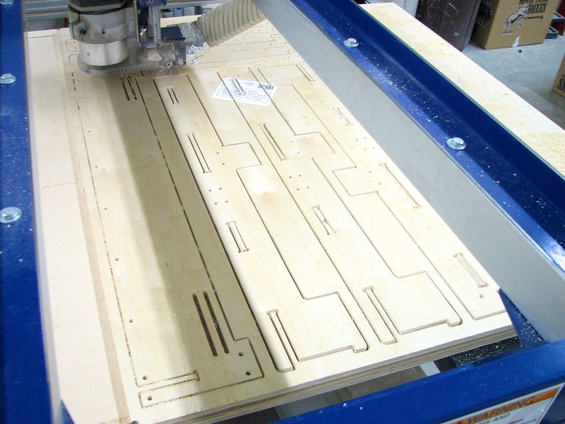
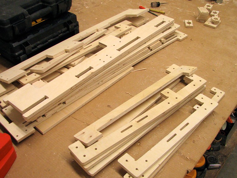
The structural design was based on 1/2″ plywood, cut to shape with a CNC router.
The piston walls were constructed of high-temperature UHMW polyethylene and the piston floor was topped with a gum-rubber surface that made a tight seal against the four walls. The build volume was 8.5″ x 11″ x 17″.
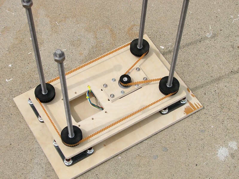
The motion control systems in the three axes were based on beefy stepping motors and timing belts. The Z axis was driven by a single stepping motor, driving a double-sided timing belt that turns four acme screws to lift the piston. The X axis, which moved the Main Carriage, or Gantry, that includes the whole Y axis, was driven by dual acme lead screws on either side of the machine, which are in turn driven by a single timing belt from a stepping motor. The Heater Carriage, which held the heating element, was attached directly to the a timing belt driven by a smaller stepping motor. The Heater Carriage position was constrained by two linear shafts.
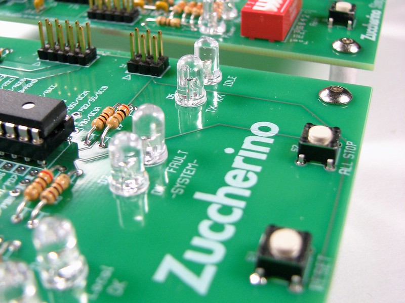
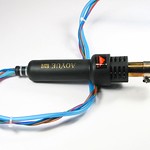
As part of the design, we also built a new third-generation heater that had a stainless steel housing and nozzle. And, we reworked the electronics from being a handwired mess into something almost elegant. The platform was called “Zuccherino” for the italian term meaning “sugar cube” (in the idiomatic sense). The name is meant to be suggestive of both the modular nature of the CandyFab control electronics platform, and the fact that it works with sugar. As an Arduino derivative, its name is also reminiscent of the name Arduino and those of its clones, while minimizing abuse of the Italian language.
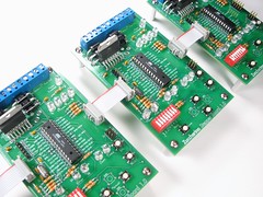
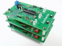
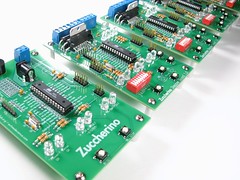
The Zuccherino platform is a series of small semi-independent microcontroller-based circuit boards, in several different flavors. Each type of Zuccherino board is dedicated to a single control function and sports the necessary hardware to carry out that single task. For example, the “Zuccherino Stepper Board” controls a single stepper motor.
In a working setup there is exactly one Zuccherino Master Board (that serves as the computer interface) and any number of additional Zuccherino boards of other flavors. For example, a minimal CandyFab setup might use five Zuccherino boards: One Master Board, three Zuccherino Stepper Boards to control the three cartesian axes, and one Zuccherino (solid state) Relay Board that controls the heater. We also developed a servo motor controller board that (like those on the CF4k) could control a DC motor equipped with a quadrature encoder.
There were a lot of promising things about the CandyFab 5000, its mechanics, and its control system. Unfortunately, our CNC manufacturing plan hit a wall. (The wall was human in nature, not technical. See the Epilogue for more discussion.) For the sake of manufacturability, we ended up making the decision to start over again from scratch, this time with a design that could be fabricated on a laser cutter.
We had already spent nearly a year on the CF5k, and it didn’t make sense to continue pouring time and effort into what had suddenly become a dead-end development path. Back to the drawing board we went. The CandyFab 5000 never saw “first melt.”
The CandyFab 6000

In the spring of 2009, we finished designing and building the third-generation CandyFab, the CandyFab 6000. It came with a spiffy new logo.
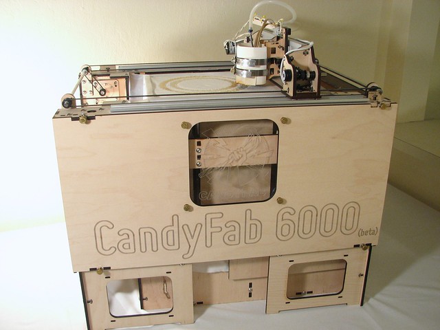
Like its predecessor, the CandyFab 6000 was essentially an all-new design using off-the-shelf parts wherever possible. The structural design was based on high-end 6 mm plywood which can be cut to shape with a CO2 laser cutter. Careful planning went into picking components and materials that are accepted for use with food where possible and/or necessary.
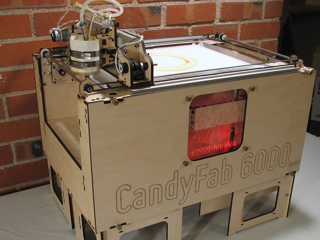
Unlike the previous versions of the CandyFab, the CandyFab 6000 was designed as a “benchtop” 3D printer, not as a floor-standing model. The build volume is 8.5″ x 11″ x 7″ deep. Much smaller, but still a respectable 10 liters. (Subsequent models could have been made larger again.)
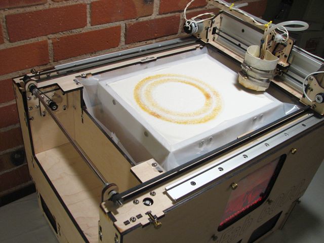
The motion control systems in the three axes were based on servo motors (DC motors equipped with quadrature motors) and timing belts. The Z axis was driven by a single servo motor that drives a timing belt that turns four 3/8-12 acme screws to lift the piston. The X axis, which moves the Main Carriage, or Gantry, that includes the whole Y axis, was driven by dual timing belts on either side of the machine, which are in turn driven by a single timing belt from a servo motor. The Heater Carriage, which holds the heating element (“oven”), was attached directly to a timing belt driven by a smaller servo motor, and constrained in position by an off-the-shelf dust-resistant linear slide. Most exposed bearings in the CandyFab 6000 design are plain (as opposed to ball) bearings made from dust-resistant high performance composite materials. Sugar is dusty.
A washable cotton “culinary” liner provided a food-safe seal around the edges of the piston. Food-safe UHMW HDPE funnels (gutters) around the edge of the piston can return unused media to a storage tray beneath the unit.
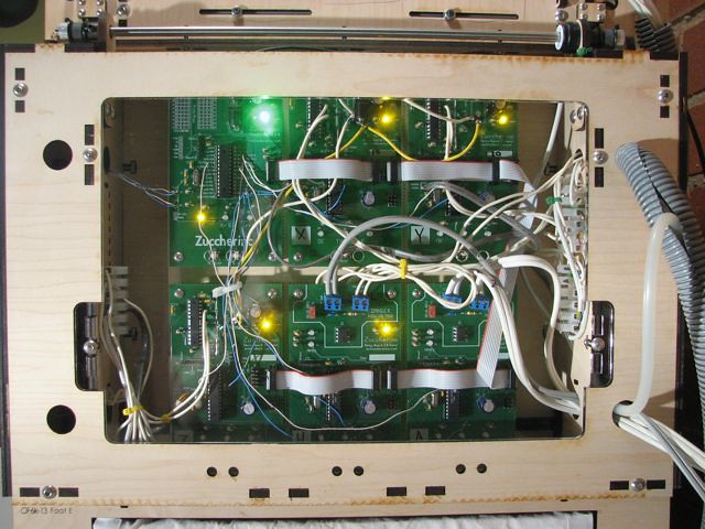
The CF6k still used the same Zuccherino control system designed for the CF5k, with some hacking to make everything work. The Zuccherino modules were master (1), XYZ servo motor drivers (3), and solid-state relays (2), to drive the heater and control the air flow by regulating power to the aquarium air pump.
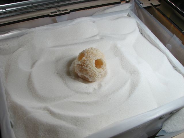
By the time we started printing with the new machine, it was already producing output as fine as the best we had ever seen on the CandyFab 4000. On the one hand, that was great. On the other, there is a very real sense in which we hadn’t made any progress (other than the shape of the machine!) after spending two more years working so hard on the project.


Photo credit (both): Scott Beale / Laughing Squid.
Epilogue
The CandyFab 6000 made its debut in 2009. That was the same year that MakerBot was formed, and the year that hobbyist 3D printing exploded. Suddenly, you could just buy a credible 3D printer for $1000. The primary motivation for making the CandyFab was no longer there. 3D printing also became much more accessible as services like Shapeways grew in popularity and dropped in price.
The CF6k was itself a credible machine that could have made an excellent kit with a little refinement, but that was not to be the case. Eventually, the CF6k was (literally) set on a shelf, and began to acquire dust.
What went wrong with the CandyFab project? We could make a long list. But to be fair, the fate of the CandyFab project was determined more by “making different choices” than by “making mistakes.”
Still, there are stories to tell, and lessons to learn.
- Premature publicity is wonderful and terrible. When the CF4k made its debut, there was an incredible burst of interest and publicity. We had our pictures in Wired Magazine, for goodness sake. But we didn’t have a printer to sell, and this was in the days before Kickstarter. The CF4k was built out of surplus junk. It was not a manufacturable design. There was a lot of work cut out for us before we would have a CandyFab that could be sold. One might label that as a “rookie mistake,” and there would be some truth in that statement. On the other hand, what happened was also just the natural result of setting out to build something amazing, as opposed to designing a product that would eventually be sold.
- A side effect of the premature publicity that we did not anticipate was the number of individual queries that we received about the project. A lot of people wanted to help. But, for the first few months after its debut, we spent much more time answering questions than actually working on the project.
- The CF5k was a disaster. We spent the ten months following the debut of the CF4k working on a new, manufacturable design, the CandyFab 5000, that was to have made its debut at the 2008 Bay Area Maker Faire. Our good friends with a CNC woodworking shop agreed to help us build it, but put it so low on their list of priorities that the prototype didn’t get finished in time for Maker Faire. More than anything else, this derailed the momentum of the CandyFab project. Without being able to rely on using CNC woodworking for eventual manufacturing, there was no real point in finishing the prototype. We purchased a laser cutter, and started over from scratch. Ten months after that, we had the CF6k, which could be built from laser-cut parts. But in the course of making the CF5k, we had lost a year, the momentum of the project, and those friendships. The project never really recovered.
- We were busy. We had day jobs, and a growing kit business on the side. Part of our motivation for starting the kit business was to provide some funding for the CandyFab project. It did provide a little money (for example, to buy that laser cutter) but also soaked up an increasing amount of time.
- Designing and building these CandyFab machines was an enormous investment of time and money. We could scrape together the time to work on them, but it became harder and harder to justify the expense of new versions, since nothing was quite yet at the stage that we could talk honestly about selling anything. If we had gotten to this stage several years later, crowdfunding would have been an excellent solution.
- While we had personal access to many of the venture capitalists here in Silicon Valley, we weren’t in a situation where we could really seek outside funding. Getting investors is (often) a full time job. And we already had jobs, and a side gig, and CandyFab on top of all that. In the intense startup culture here, it’s hard to imagine that anyone would fund a project run by people who hadn’t already quit their day jobs for it.
- Eventually, while we worked on other things, the runaway success of other hobbyist 3D printers made it possible — heck, easy! — for almost anyone to have their own 3D printer at home. We had set out to be the people who had their own 3D printer, and we had accomplished that. But the writing was on the wall. Soon, there would came a time when everyone else did, too. Did we want to become yet another “also ran” 3D printer maker? Not really, no.
Finally, it’s worth noting that a company eventually formed to make 3D printers in sugar— starting in a sense from the point at which we left off. And their work has been amazing.
Our work here is done.